

Input
 1. Input Selector Switch is the global input sensitivity control which selects the amplification level for both mic and line level signals on a 12 position rotary switch. Five line positions (-6dB to +15dB) are available inside the bounded portion of the switch (11-3 o’clock on the dial) with Unity Gain at line level denoted by the open circle at 12 o’clock.
Mic Positions begin at 4 0’clock and provide a maximum gain of +65dB in the 10 O’clock position.
Via the state of the 1970 art magic of the sensitivity switch, input signals are routed throughout the custom wound Sowter AW27 input transformer for Mic, Line and Direct input signals.
Important to note, our line input is not simply a pad in front of the input transformer. The mic pre amp and the line pre amp are two completely discrete amps that are tuned differently from each other for specific use. The Line pre amp is as full bandwidth as reasonable, designed with mixing in mind. The mic amp is in comparison bandwidth limited for a much more “in your face” sound. Bandwidth limited, why would you want that?? Because it sounds *incredible*. You’ll see.
2. Phantom Power Switch sends 48v Phantom Power to the XLR output for powering microphones and direct boxes when switched to the right.
2A. LED will illuminate to indicate Phantom Power is on. It is a good practice to engage this switch only after your mic is plugged in and off before unplugging the microphone. Consider this step to your work flow especially if you are using a TRS (phone or TT) patch bay with the units. It is optimal for your mic to see 48v on both its hot (XLR pin 2 in most places in the world these days) and cold (XLR pin 3) legs simultaneously. When using a mic with a phone patch bay, the tip of the connector (hot, pin 2 equivalent) will make contact before the ring of the connector (cold, pin 3 equivalent) which, over time, can lead to damage to your mics if “hot patching” with phantom power on.
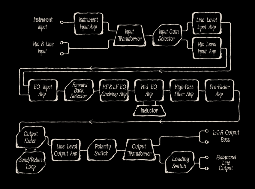
3. Direct Instrument Input Jack is a DC coupled switched jack actuated by inserting a 1/4″ phone plug for any high impedance, low level signal: instruments. This input is optimized for passive pickups (guitars, basses, pedal steel, electric pianos, clavinets, etc) and also works well with instruments with active outputs like synths, mellotrons, combo organs, etc. Referencing the block diagram, you can see that the Instrument Input Amp is located before the Input Transformer whose gain is selected via the Input Selector Switch just like the mic and line level inputs. See the diagram.
Output
 4. Output Fader Pot sets the level for the audio sent to the final amplifier stage. Unity Gain is “Full On” in the three o’clock position. Unlike a fader on most consoles, there is no “gain in hand” and will only attenuate your signal as you turn the knob counter clockwise from the “Full On” designator. For Expert Level operation, experiment with the carefully crafted distortion available in the Channel Amp by dialing down the output fader counter clockwise and adjusting the input sensitivity switch for Maximum Awesome. Those familiar with guitar amplifiers that have a “gain” and “master volume” control will find this fader works to achieve a similar end effect. The Fader Pot fully counterclockwise in the six o’clock position will mute your channel amp in a mix scenario. The taper of this pot lends itself wonderfully to creating beautifully smooth fadeouts on program material.
5. High Pass Filter Switch engages a 12dB / Octave high pass filter (or low cut filter) at 130 Hz when switched to the right. The high pass filter is critically located at the output of the EQ network and is much much more than a simple “rumble filter” in the front end of the mic preamplifier, here’s why:
Elaborate saturation can be achieved with the strategic use of this switch. Experiment with boosting the low shelf to the maximum and then engaging the high pass filter: this will allow the Low Frequency Shelving Amplifier to saturate while cutting the low frequency output to a more “usable” level. This is a very very handy tool to not overlook and opens the door for creative gain staging possible with the Awesome Channel Amp.
6. Polarity Reverse Switch flips the phase of the signal when engaged to the right. The location of the flip is also critically located after the Line Level Output Amplifier so any nonlinear distortion generated is flipped as well, turning the Polarity Reverse function into yet another tone shaping device beyond its immediate function.
7. Output Transformer Loading Switch is a three position toggle which places a 1200 ohm load on the output transformer in the up position, 600 ohm load in the down position and removes the loading resistor in the center position. With modern high impedance inputs, a more traditional load can be placed on the output to make the output of the Channel Amp work a little harder, approximating a more classic tone via a modern bridging input (as seen on an A-D converter for instance).
8. Passive Mix Buss Switch assigns a secondary winding of the AW26 Output Transformer to the Left (up) Center (middle) or Right (down) mix buss for passive mixing. Just like the best designed vintage consoles, the passive buss is set at 150 ohms and at Mic Level, so any standard mic pre can be used to make up the gain on the summing buss. The feed for the buss is taken from a secondary winding of the output transformer that is in every way identical to the main direct out, so all of the tone that has been carefully dialed in on the mains gets fed to the buss.
The most practical use for the mix buss will likely be summing stems from a DAW. Set up your submix in stems and output to your Awesome Mixer and you have a VERY powerful system at your fingertips. A completely self contained 8×2 mixer for summing a DAW can be setup with ten AwTAC Channel Amps and two ten space racks.
During my initial testing with the Awesome Mixer, I gravitated towards using two mics on a guitar cab, each plugged into a Channel Amp and then bussed through the mix network to a third Channel Amp and got some of the best guitar tones I have ever been able to create to date. I could easily see this being a standard mode of operation on tracking sessions for myself in the future.
Why not just record those two mics through the Channel Amps to two separate tracks and combine in the mix? Well, first off, that eliminates a whole set of decisions to struggle with during a mix. For my work flow, streamlining mix decisions is absolutely advantageous. Second, and most important, the mix buss has a sound and it is epic (epic as in truly Epic, not Bedford Ave epic), when you take a listen to it you’ll see… By using three of these in a 2×1 configuration, that guitar sound is passing through 18 discrete amplifiers, 6 transformers and 2 inductors. The sound that can yield is gargantuan and thick. A sound that Ray Harryhausen would have animated (replete with four heads, dreaded fur and talons dripping stop motion poison). The Channel Amps were tuned to get bigger and bigger when adding more channels in series and a 2×1 summing arrangement is the fastest conclusive experiment you can conduct to prove this to yourself.
EQ
 9. Equilizer Network Control Switch engages the Awesome EQ to the right and bypasses the EQ to the left. For maximum amplifier saturation, it is suggested to “zero” the EQ pots and leave the EQ engaged if you don’t want the EQ, yet want the largest sound possible out of the box. Bypassing the EQ removes three amplifiers in series from your signal path.
This switch (like all the switches on the AwTAC Channel Amplifier) is a super high quality, gold plated switch designed to provide years of noise free operation. Audio does however, pass through this switch (ie, this switch does not control a relay) and as a result can induce a “click” when operating the switch just like every single classic discrete transistor desk from the 70’s did. This circuit is not designed to be switched in and out “on the fly” while recording a track or mix.
10. Baxandall High Frequency Shelving Amp Pot for dialing 12dB of boost or cut, frequency selected by
10A. High Shelf Frequency Select Switch is a three position toggle which selects 11Khz in the up position, 6Khz in the down position and a 17khz “air” band in the center position.
11. Mid Amp Pot for dialing 12 dB of boost or cut, frequency selected by
11A. Mid Frequency Select Switch is a ten position rotary switch which selects eight frequencies (300hz – 8 Khz) available on the inductor based mid band EQ. 1K and 3K each have two positions on the rotary dial for a wide (normal) and narrower Q.
12. Baxandall Low Frequency Shelving Amp Pot for dialing 12dB of boost or cut, frequency selected by
12A. Low Shelf Frequency Select Switch is a three position toggle which selects 70hz in the up position, 35Hz in the down position and 130Hz in the center position.
13. Forward / Back Switch is our expert level control which alters the coupling of the EQ network to the output stage of the channel amp. As a result, this switch will only have an effect when the EQ is engaged. This is a very subtle control which directly effects the way your track will “sit” psycho acoustically in your mix. It is most noticeable as a cumulative effect. A good way to strategically learn the most effective use of this switch is by assigning it to groups in your mix. For example: Track or Mix all of your drums and bass “Back” with guitars and vocals “Forward”. Now reverse. You should notice that your mix will sit with a different image or tilt. It’s very handy for adding some “space” to your mix without having to plug in a different amplifier type. This “space” should be typically most noticeable in how the low end will sit in your mix. This can be used to subtly add depth or bring things forward in a way that EQ or high pass filtering wont do. Be patient and creative experimenting with this switch, rewards are to be discovered…. Switching in real time on a single track will not produce an epic change but it’s cumulative effect is quite obvious to hear over the landscape of a full mix.
Extra Awesome Feature
Our commitment to making the AwTAC Channel Amplifier the heart of a mixing system is not casual. All units produced from serial number 51 onward come with an (awesome) option to use an external fader if you are using a Purple Audio Sweet Ten rack to power the Channel Amps.
The pin header (located on the Amplifier Board) comes set from the factory to use the internal fader only (INT default on the Amplifier Board silk screen).

But if you have external faders, simply re-orient the pin headers

as shown EXT on the Amplifier Board silk screen


Purple Sweet Ten Inupt Output
and now the Purple Audio Sweet Ten Option Input (IN 2) is set in series with the Channel Amplifier’s internal fader. As such, it is critical that the internal fader be set to “Full On” so there is no additional load put on the fader circuit.
The Sweet Ten Option Input (or IN 2 on current units) is a TRS Jack and your fader should be wired Tip – > Top, Ring – > Wiper, Sleeve – > Bottom. The Tip is your send, Ring receive and Sleeve is ground (shield). It is recommended to use a cable with the best shield possible when wiring your external faders as that ground reference determines how close to minus infinity your fader will fade out.
 Since every Amplifier stage in the AwTAC Channel Amplifier is outfitted with either a) appropriate amount of Awesome or b) maximum amount of Awesome it comes as no surprise to mention that just like our output amplifier, the pre fader amplifier will drive either a 10K or 600 Ohm external fader. This allows you to hook up a nice new P&G conductive plastic fader or if you are in the old school, plug in some old school carbon Duncan 600 ohm faders for extra vintage mojo goodness, just like lab coat guy would have done back in the day. Designed to drive either, without breaking a sweat, without hesitation.
But wait, there’s more!
You may be saying to yourself, “Im never going to have long throw faders, this is silly and will never apply to me.” Well, it is lovingly called Awesome Channel Amplifier for a reason and we want that to apply to everyone, so check out what else you can do with the fader loop:
While we designed the loop to be used with a fader, ultimately all it is is an unbalanced insert, and it can absolutely drive 600 ohms, so you can totally use the insert to stick any piece of gear in there, most conveniently: a compressor.
Thats right kids.
![]() You can connect a Compressor or Limiter to the AwTAC Channel Amplifier post EQ and post fader, pre output, pre buss assign. This means of course, that whatever piece of gear you use on the insert will show up on both the main direct out and on the buss as well. Just when you thought it could get no more Awesome.
You can connect a Compressor or Limiter to the AwTAC Channel Amplifier post EQ and post fader, pre output, pre buss assign. This means of course, that whatever piece of gear you use on the insert will show up on both the main direct out and on the buss as well. Just when you thought it could get no more Awesome.
Surely there are some people that may have reservations about an unbalanced send and return, but do realize that most of the consoles that built the sound of rock in 1970 had insert points that were unbalanced, identical to this. If your wiring and grounding is solid, it shouldn’t be an issue.
The signal on the send sits at nominally 9dB below line level while being able to drive 600 ohm compressors to +20dBm. This is not a problem for the vast majority of compressors out there past and present, simply adjust any input, threshold, and output controls to compensate.
Certainly any compressor with modern bridging input will have no problem receiving the send signal as well.