Channel Amplifier In and Out
The double wide enclosure of a Channel Amplifier will occupy two slots in a 500 rack. The diagram below shows the input and output locations on each module.
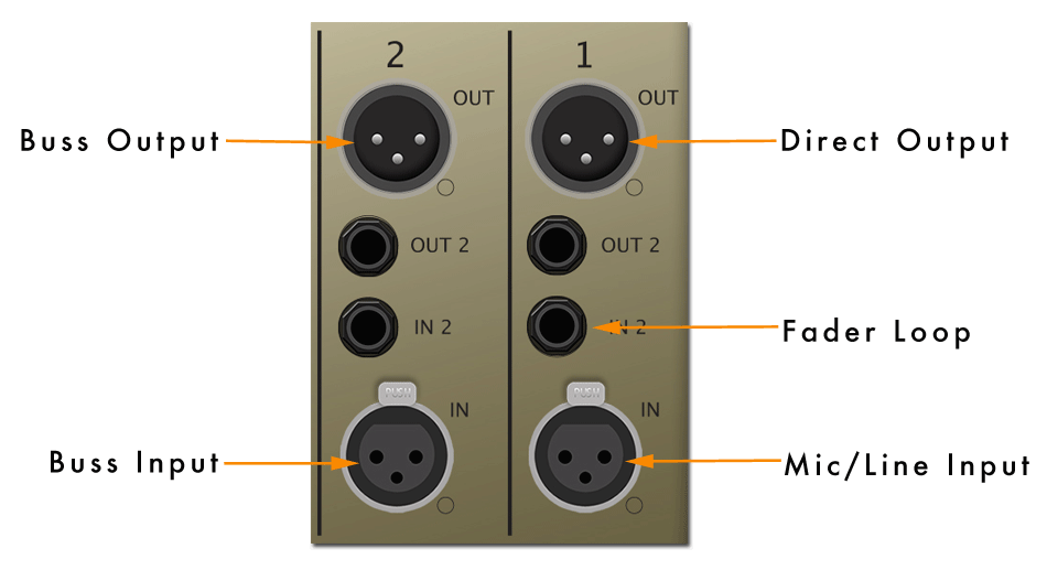
The Right side of the module should be familiar, with a standard Mic and Line level input on the female XLR and the direct Line Level Output on the Male XLR. The Fader loop can be patched using the In 2 TRS connector on a Purple Audio or similar rack.
The left side of the module contains the patch points for using the LCR mix buss in each Channel Amp. The Mix Buss Output is fed from the Male XLR and the Mix Buss Input is received on the Female XLR.
Patching the Mix Buss
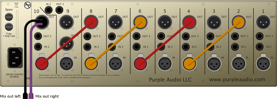
Patching a rack of Channel Amplifiers as a mixer is a relatively simple affair. The mix buss of all the units that will comprise your mixer need to be daisy chained together, and this is done using standard XLR cables. As illustrated above, the top male connector on the left or “EQ side” of the unit is the Mix Buss Out. This is where the Mix Buss Assign switch sends the buss signal (pin 2 left, pin 3 right with a common ground). The bottom left female connector is the Mix Buss Input. The Mix Buss Out from one unit gets patched to the Mix Buss Input of the next unit in the chain.
Once you’ve patched as many Channel Amps together as you would like, the FINAL Channel Amp in the chain requires the Mix Buss Output cable. (Important to note, this is not simply a “Y cable” and if a simple “Y cable” is used, the mix buss will absolutely not function properly. There are mixing resistors in the breakout cable itself which are critical to the proper function of the passive mix buss!) Patch the Mix Buss Output Cable into the Mix Buss Out of the final unit in your chain and then patch the two leads of the breakout cable to the mic pre of your choice to make up the gain (and add color) to your Buss. The output of the mic pre’s you have selected will be the summed L / R program material of all the AwTAC Channel Amps you have chained together.
The diagram below illustrates how five Channel Amps in a Sweet Ten would have the Mix Buss patched for use in a 5×2 setup.
Twenty Channels (four ten space racks) can be patched like this without any modification to the mix buss.
This is what is going on under the hood of all the (really good) mixing consoles out there, it was important to us in the development of the Channel Amp to bring full mixing capability to any common 500 rack on the market today. The irony of the history of the 500 format was not lost on us at the Awesome Transistor Amplifier Company. For years it seemed odd that there were so many racks out there, whose origin of course, was the frame for a mixer, however none of them (with the exception of a Purple Audio Sweet Ten) could be easily be setup for mixing. We wanted everyone with a rack to be able to use it as a mixer, not just a housing for mic pre’s and EQ’s.
The mix buss was not a feature added on so we could have another switch on the unit, it was the center of the design of the Channel Amplifier, the entire unit was designed, from the ground up, with the idea of a mixer platform in mind. And this mix buss sounds *good*. Really, really, really Good.
The Mix Buss Output Cable is included with the purchase of two or more units or can be purchased as an add on item as you build your Awtac Mixer over time.