Channel Compressor is:
- Single width 500 module
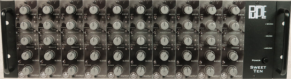
10 Channel Compressors fit in a Purple Audio Sweet Ten rack - A Mono FET Compressor
- with
- A Line Level Amplifier
- for
- True Parallel Compression
Features
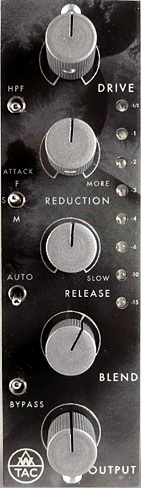
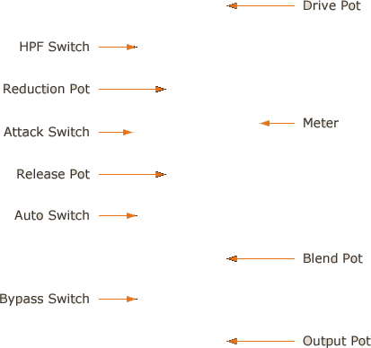
Drive Pot sets the level to the FET Controlled Amp in the compressor circuit. Below unity, the Drive Pot will raise the level fed to the compressor. Above unity, the Drive Pot will raise the level of distortion in the compressor. Since the sidechain will not distort the FET controlled amp, the Drive Pot is there to add distortion when desired.
HPF Switch engages a 6 dB/ Octave High Pass Filter to the side chain at 375 Hz. Seems like a high cut off point until you listen to it, the gradual slope allows your low end to breathe for a much more natural sounding vibe. Absolutely excellent on program material.
Reduction Pot controls the amount of compression applied to your input signal. Turn clockwise for more compression, fully counterclockwise for Off.
Attack Switch is a three position toggle switch which selects Fast (1.5 mS) in the up position, Medium (15 mS) in the down position and Slow (40 mS) in the middle position.
Release Pot sets the release time from 75 mS to 3.4 Seconds. Fastest setting is full counterclockwise.
Auto Switch engages an auto release circuit when the toggle is in the up position. When engaged, Release Pot orientation has no effect. The auto circuit is program dependent and very, very, smooth.
Blend Pot is the fader for the Blend Amplifier which sets output level for the Parallel, uncompressed, circuit. Only the Parallel Blend signal is effected by this pot. Blend circuit provides +9dB of gain “in hand” similar to what is found on a proper console. Unity gain is denoted by the hash mark at 1 O’ Clock. Full Counter Clockwise mutes the Parallel Blend signal.
Output Pot is the fader for the Make-up Amp which sets the output level for the Compression Circuit. Only the compressed signal is effected by this Pot.
Bypass Switch activates the relay controlled true bypass. In the up position, the compression and parallel blend circuits are engaged. In the down position the entire circuit AND transformers are bypassed at the edge connector: input signal comes in off the edge connector, through the relay and back out to the edge connector completely bypassing the Channel Compressor circuitry. When powered off, the unit defaults to “bypass” so signal will flow through with the rack off, no need to unpatch.
Meter is an 8 segment peak detecting LED meter which displays gain reduction only in the following steps: -0.5 dB, -1 dB, -2 dB, -3dB, -4 dB, -6 dB, -10dB, -15dB The meter is always on, even with the unit in bypass.
It’s a FET Compressor with a Soft Knee
The AwTAC Channel Compressor is a versatile, classic (if not elegant) sounding compressor with simple to use controls designed to stack well in a mix while providing everything from “just a little” to “suck all the air out of the room” amounts of compression. Our approach was to design an old sounding, not overly modern behaving compressor that can sound great on every channel of a console, build up well in a mix and be very quick and easy to get dialed in.
The AwTAC Channel Compressor has a great subtle vibe which wont accidentally do too much, is never too grabby, and can easily be dialed in from fairly transparent operation to completely in your face. It does this effortlessly while maintaining a feels like it’s London 1970 attitude.
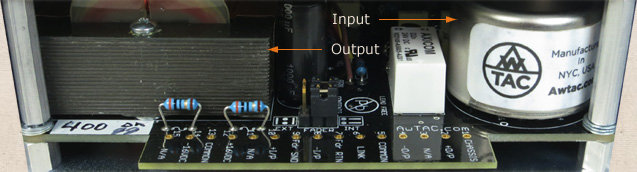
The AwTAC Channel Compressor is transformer balanced on its input and output for big iron sound and weight.
Every single stage in both the audio and sidechain circuit is comprised of carefully tuned discrete transistor amplifiers.
The AwTAC Channel Compressor features a 10K bridging input that will not load a converter feeding its input.
The AwTAC Channel Compressor attenuates input signal after its input transformer, so it is possible to drive high level to the input for more transformer coloration if desired.
The sidechain uses a FET for its control element, which controls the gain of the input amplifier. The FET is in the sidechain only, the input amp is a bold sounding bipolar transistor amplifier which could work as the line level receiving amplifier in a console.
The FET sidechain does not shunt signal from the input amp, but rather controls the gain of the input amp, so its easy to think of the sidechain as somewhat of an “auto-fader” if such a thing existed. What this makes for is a very very smooth sounding compression circuit that, while FET controlled, tends to feel a bit like an optical type compressor. The circuit maintains all the speed usually associated with FET compressors but has a very, very smooth quality commonly associated with optical compressors.
The Meter
 The AwTAC Channel Compressor’s LED meter is a VERY fast, very accurate peak detecting meter that reads the DC sidechain only. This meter will only ever show the gain reduction in the sidechain, it will never effect the audio path and it is always on. When the Channel Compressor is in bypass mode, the meter will still illuminate if you are feeding signal to the unit.
The AwTAC Channel Compressor has a soft knee compression characteristic. Onset of gain reduction past the threshold is gradual, beginning with a 1:1 ratio and climbing to 10:1 where it remains. Since a lot of useful leveling occurs in this sensitive transition, Displaying good resolution in the first 4 dB of gain reduction was paramount, five out of the available eight segments on the meter display the first 4dB of reduction.
Traditional mechanical GR meters (VU) aren’t usually fast enough to detail this sort of activity, which often results in too much compression occurring by the time you really see the meter moving.
Not the case with Channel Compressor where individual LEDs for -0.5dB, -1dB, -2dB, and -3dB show instantaneously the first half of its compression slope.
Four more LEDs, -4dB, -6dB, -10dB, and -15dB then show how the second half of the slope becomes steeper before leveling off at a max gain reduction amount just past the last light.
A very subtle soft knee compression eases in just before the meter lights, taking off a nominal fraction of a dB, the first segment of the meter lights once the compressor is into 0.5 dB of reduction.
The meter is designed to show “subtle compression” to “some compression” to “compression” to “lots of compression”. Don’t be afraid to light it up, “maximum compression” is off scale.
The Sidechain and You: Use
Using the Channel Compressor is a very straight forward affair, with emphasis placed on a “use your ears” approach.
Drive Pot adjusts signal level coming from the input transformer and going to the FET-controlled amp (where gain reduction takes place).
Unity gain is at center (12 o’clock). Turning the Drive Pot clockwise from center amplifies the incoming signal (boost). Turning the Drive Pot counterclockwise from center attenuates the incoming signal (cut).
If the signal level is low (less than -4 dBu), Drive can be used to boost it so that the desired amount of compression may take place.
If the incoming signal level is circa 0 dBu or higher, Drive can be used to boost this signal further, perhaps overdriving the FET-controlled amp for some tasty AwTAC distortion.
If the incoming signal level is too high and you want to avoid distortion, simply turn the Drive Pot down (counterclockwise).
Reduction Pot controls the amount of gain reduction.
Turning the Reduction Pot clockwise will increase compression. When Reduction Pot is turned fully counterclockwise, compression is OFF, and you can then use Channel Compressor as a line amp or coloring device.
Because the AwTAC Channel Compressor is a feedback style compressor, Drive and Reduction Pots can be used interactively.
If there’s only a few dB of compression taking place, then turning up the Drive Pot will not only increase level to the FET-controlled amp, but may also increase the amount of compression. However, if there’s already a lot of compression taking place (i.e. Reduction knob is cranked!) then the Drive knob will have little effect on how much compression takes place, instead becoming a sort of distortion, over-compression, and “depth” control. In this way, you can turn down the Drive control for basic leveling of peaks, or turn up the Drive control to bring out low-level aspects of the signal such as room ambience.
But what about threshold? What about ratio?
This is isn’t a VCA compressor, it’s a classic FET leveling amplifier, made like our wise elders in rock would have in 1970. If you want a lower threshold, turn up the Drive and Reduction knobs.
Don’t worry about the ratio, it’s adaptive. It’s nominally 10:1 once compression really gets going, but it eases into that number, beginning at 1:1 and transitioning to 1.5:1 at the bottom of the soft knee slope (that’s what the -0.5 dB LED is for), then 2:1, then 3:1, 4:1, 6:1, and… 10:1! Notice how we scaled the gain reduction metering to match this slope? If you keep increasing compression past where the meter runs out a 16:1 ratio is possible along with limiter type characteristics.
In a typical line level scenario, we’d recommend as a starting point to set the Drive and Output pots to around noon, have a listen and dial in from there. There is over 80 dB of internal gain inside each Channel Compressor, powering up with the Drive and Output full on may cause the unit to oscillate.
True Parallel Compression: what your Blend should be.
A Blend control commonly can be a cross fader- what is seen typically on a DJ mixer or on a wet/dry control on a reverb. This can work well in some applications but can be an obstacle when it comes to serious mixing: a cross fader always blends at the same ratio, be it 90:10, 70:30, 50:50, etc. A true parallel circuit and a compression circuit feeding an output summing amp can mix however you’d like, 90:30, 50:10, 60:60, both signal’s output level control is completely independent of each other. Adjusting the level of one has no effect on the level of the other.
The theory of operation that you would apply to mixing with parallel compression on a console can be directly applied to using the AwTAC Channel Compressor. This isn’t like compressing in parallel. It is compressing in parallel. No tricks. No shortcuts.
Consider how to patch a compressor in parallel with a track on a console in the following example:
Playback feeds channel 14 on the console, and get bussed to the compressor.
The compressor output then gets returned to the console on channel 28.
Now you have two faders on the console: uncompressed playback on channel 14 and the compressor return on 28.
The compressor is working in parallel with the original track that is feeding it. Patched like this, an engineer has full independent control of the level of the uncompressed track on channel 14 and the compressed track on channel 28. This opens up an endless field of creative techniques.
The Output and Blend controls on the AwTAC Channel Compressor work in every way identically to this, they are two independent signals in parallel which combine in a summing amp before the output.
Each Channel Compressor has a dedicated line amp which receives the clean, uncompressed signal from the input, the way that channel 14 in the above example does. The Blend Pot is the fader which feeds that clean line amp. The Channel Compressor Output Pot is the fader that feeds the Makeup Amp, which functions the same way that channel 28 in the above example did.
Similar to the two faders on the console in the example, the AwTAC Channel Compressor’s Blend Amp and Makeup Amp both passively sum to the Output Summing Amp. Inside of every Channel Compressor, there is a 2×1 mono summing buss combining the two signals, summing the two signals just like a console would do. Additionally, similar to a fader on a console, the Blend fader has +9dB of gain “in hand” available above unity.
With the AwTAC Channel Compressor you can take your input, set the uncompressed level to your desired level with the Blend Pot (unity gain is 1 O’Clock on the pot denoted by the hash mark on the dial) and then with the Output Pot bring up the compressed signal under it. You can set the compressed level to unity and bring up the parallel blend behind it to air it out. Of course you don’t need to use the blend circuit at all, simply rolling the Blend Pot back full counter clockwise will mute the circuit and you’ll have a conventional compressor.

( ( ( S T E R E O ) ) )
The AwTAC Channel Compressor is designed for Stereo use.
Units are stereo linkable following the API standard of merging Pin 6 on your rack for DC linking.
We are very serious about stereo matching at Awtac and there are several parts in the Channel Compressor that are measured, selected and matched entirely by hand. It is labor intensive, but there is no other way to effectively guarantee tight stereo tracking between units:
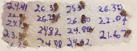 The sidechain FETs are individually measured by hand, selected and matched in stereo pairs for offset between channels.
One of the problems commonly found in vintage FET compressors when it comes to stereo linking, is one channel reacting a dB off from the other, which pulls the stereo image to one side. Typically, this is caused by offset between the two sidechains. By matching FETs in the sidechain for offset, this problem is minimized.
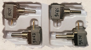 All the pots on the Channel Compressor are individually measured by hand, selected and matched within 1/10th dB for use in Stereo.
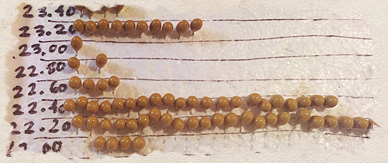
The timing capacitors are individually measured by hand, selected and matched so the release tracks as close as possible between left and right units.
 A stereo pair consists of an odd serial number and the sequentially higher even serial number. IE, 1 & 2, 37 & 38, 145 & 146, etc constitute matched stereo pairs.
Each AwTAC Channel Compressor of course works stand alone in mono.
Passion for Distortion (Won’t Clip Your Converter)
The AwTAC Channel Compressor has a maximum output level of +18 dBu. This means no matter how far you crank the OUTPUT and/or BLEND knobs, Channel Compressor won’t produce an output signal greater than +18 dBu without egregious distortion.
What is +18 dBu?
Typical high output magnetic tape reaches saturation around +17 dBu, and typical Analog-to-Digital converters will probably clip at +20 dBu (if calibrated for +4 dBu = -16 dBFS).
Most analog consoles and outboard gear produce a max output level of at least +22 dBu, which means they clip last.
We wanted to make sure the Channel Compressor would clip after tape but before digital.
Why?
AwTAC Amplifiers are designed and tuned to sound Awesome when clipping.
A great deal of time is spent listening to the distortion the amps make and keeping that distortion sounding cool during the tuning process. By setting the clipping level lower, it allows for the user to push Awtac gear towards or into distortion while being able to record a clean capture of it without distorting the input of the converter.
In this fashion, a clean recording of the maximum vibe possible is allowed to be made. Of course there is as much clean headroom as you’d ever need on a digital system, but if you want to dial in more color, you can dial in ALL of it before your converter is overloading.
Combining a +18 dBu output level along with an input transformer that is pre-attenuator, the input and output can both be driven for as much color as desired.
Ultimately, the AwTAC Channel Compressor is a clean sounding device, however, it is tuned to sound great when pushed to it’s limit.
Extra Awesome Feature: Insert Loop
Like Channel Amps, each Channel Compressor has an unbalanced insert loop inline with the Output Pot. This allows for an external long throw fader or line level device (like an EQ or another compressor) to sit in the fader loop accessible via IN 2 on a Purple Audio Sweet Ten rack.
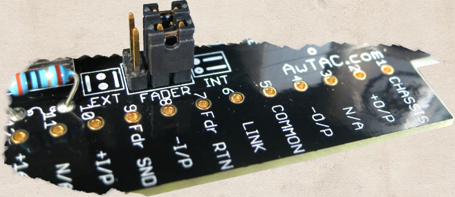
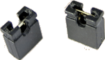
Simply reorient the pin headers on the circuit board and plug your device into the loop. The loop will drive 600 ohms or 10k.
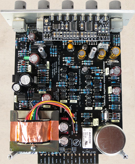
What’s it made of?
The AwTAC Channel Compressor was designed and manufactured with the same ethic present in our other products. Only the best through hole capacitors and transistors are used, and each is selected for the sound they make. This yields a specifically tuned circuit that a chip could only provide by accident. Metal film resistors, sealed conductive plastic pots, gold plated switches, gold plated relays, gold plated pin headers and gold plated PCB contacts round out the package.
The entire AC audio path is through hole, discrete construction.
The entire DC side chain is through hole, discrete construction.
Our DC Meter is surface mount. As an ardent proponent of through hole construction (almost to a last of the V-8 superchargers degree) this was a tough decision, but the performance available in the surface mount meter chipset is incredible. The meter of course *only* reads DC and can in no way influence the audio path. With the superior performance available, a better meter was the best decision.
The side panels are heavy gauge electroplated steel, and the module is fully enclosed for the best shielding.
Continuing our dedication to a no compromise, no accountant advised, no corner cut approach to manufacturing, the AwTAC Channel Compressor is manufactured in the United States of America as much as is absolutely possible in 2014. The front panel, side panels, knobs, circuit board, input transformer, output transformer and labor related to the manufacture of these items are all sourced from American owner operators just like us, in many cases the guy that answers the phone is the guy making the part for us. Every single dollar spent with us directly effects local economies and more importantly, directly benefits an American laborer.
Each AwTAC Channel Compressor is assembled in Brooklyn, NY by a cheery staff of dedicated audio freaks, all of whom are full time NYC residents.
It’s 1970 design done right in 2014. And we are doing it with pride, in the USA.